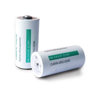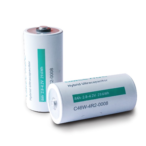


φ46mm 4.2V 8Ah HUC hybrid ultra capacitor cells
Product Description
To make up for the shortcomings of lithium-ion battery safety, power performance, and temperature performance, a hybrid ultra-capacitor (HUC) scientifically and perfectly integrate supercapacitor technology and lithium-ion battery technology (parallel design in powder), and displays both the high power characteristics of EDLC and the high energy characteristics of lithium-ion battery. GMCC optimized materials and electrochemical systems, and adopt all-pole ear laser welding technology to achieve ultra-low internal resistance, ultra-high reliability, and thermal management-safety structure design advantages; Based on the external characteristics of linear charge and discharge curve, SOC and charge and discharge control management are very accurate. By adjusting the surface capacity and N/P ratio, the positive and negative potentials are optimized to avoid negative lithium evolution, and the battery cell is intrinsically safer in the process of charging. 6Ah HUC cell can be applied to 12V cranking, 12V ADAS backup, 48V MHEV, High Voltage HEV, FCEV, and other vehicle markets.
Table 1 The main technical parameters of HUC (C46W-4R2-0008)
| Item | Standard | Note | |
| 1 Rated Capacity | ≧8 Ah | @25℃,1C Discharge | |
| 2 Median voltage | 3.7 V | ||
| 3 Internal resistance | ≤0.8 mΩ | @25℃,50%SOC,1kHz AC | |
| 4 Charge cut-off voltage | 4.20 V | ||
| 5 Discharge cut-off voltage | 2.80 V | @25℃ | |
| 6 Max continuous charge current | 160A | ||
| 7 Max 10s charge current | 320 A | @25℃,50%SOC | |
| 8 Max continuous discharge current | 160 A | ||
| 9 Max 10s discharge current | 450 A | @25℃,50%SOC | |
| 10 Weight | 315±10 g | ||
| 11 Operating temperature | Charge | -35~+55 ℃ | |
| Discharge | -40~+60 ℃ | ||
| 12 Storage temperature | 1 month | -40~+60℃ | 50%SOC,recharge once each 3 months |
| 6 months | -40~+50℃ | 50%SOC,recharge once each 3 months | |
Appearance and dimension
4.1 Boundary dimension
The boundary dimension of HUC is shown in Figure 1
Diameter:
45.6 mm (25±2℃)
Height:
94.6 mm (25±2℃)
4.2 Appearance
Surface cleaning, no electrolyte leakage,
no obvious scratch and mechanical damage,
no deformation, and no other apparent defect.
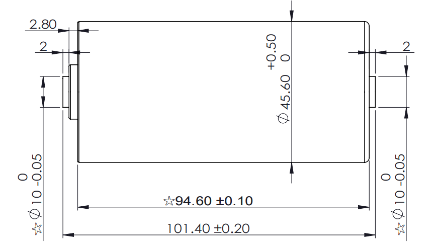
Figure 1
Performance
★Perform all tests with the HUC in good contact with the test instrument.
5.1 Standard test condition
The HUC for test must be the new (the delivery time is less than 1 month), and has not be charged/discharged more than 5 cycles. The test conditions in the product specification except other special requirements is 25±2℃ and 65±2%RH. The room temperature is 25±2℃ in the specification.
5.2 Test equipment standard
(1)The precision of the measuring equipment should ≥ 0.01 mm.
(2)The accuracy of the multimeter to measure the voltage and current should not be less than level 0.5, and the internal resistance should not be less than 10kΩ/V.
(3)Internal resistance tester measurement principle should be AC impedance method (1kHz LCR).
(4)The current accuracy of the cell test system should be above ±0.1%, the constant voltage accuracy should be ±0.5%, and the timing accuracy should be not less than ±0.1%.
(5)The accuracy of temperature measuring equipment should not be less than ±0.5℃.
5.3 Standard charge
The charge method is constant current and then constant voltage charging in 25±2℃. The current of constant current charging is 1I1(A), the voltage of constant voltage charging is 4.2V. And when the compensating cut-off current drops to 0.05I1(A) during constant voltage charging, the charging can be terminated, then the cell should be stand for 1h.
5.4 Shelve time
If there is no special requirement, the charging and discharging interval of HUC is 60min.
5.5 Initial performance test
Specific test items and standards are shown in Table 2
| Number | Item | Test program | Standard |
| 1 | Appearance and dimension | Visual inspection and vernier caliper | No obvious scratch, no deformation, no electrolyte leakage. The dimensions in drawing. |
| 2 | Weight | Analytical balance | 315±10g |
| 3 | Open-circuit voltage | Measure open-circuit voltage within 1h after charging according to 5.3 | ≥4.150V |
| 4 | Nominal discharge capacity | Discharging to the 2.8V at the current of 1 I1(A) within 1h after charging according to 5.3, and record capacity. The above cycle can be repeated for 5 times. When the range of three consecutive test results is less than 3%, the test can be terminated in advance and the average of the three test results can be taken. | 1 I1(A) capacity ≥ nominal capacity |
| 5 | Max charge current | Discharging to the 2.8V at 1 I1(A) after charging according to 5.3, and record capacity. Constant current charging at n I1(A) until the voltage is 4.2V, and then constant voltage charging in 4.2V until the current drops to 0.05 I1(A). 50%SOC: discharging at 1I1(A) for 0.5h after charging according to 5.3, constant current charging at n I1(A) until the voltage is 4.2V | 20 I1(A) (continuous charge/discharge)40 I1(A)(10s,50%SOC) |
| 6 | Max discharge current | Discharging to the 2.8V at 1 I1(A) after charging according to 5.3, and record capacity. Charging at 1I1(A) and discharge to 2.8V at n I1(A). 50%SOC: discharging at 1I1(A) for 0.5h after charging according to 5.3, discharge at n I1(A) until the voltage is 2.8V. | 20 I1(A) (continuous charge/discharge)50 I1(A)(10s,50%SOC) |
| 7 | Charge/discharge cycle life | Charge:according to 5.3discharge:discharge at 1I1(A) until the voltage is 2.8VCycling more than 5000 times, and recording capacity | Surplus capacity≥80% nominal capacityor energy throughput ≥0.5MWh |
| 8 | Charge retention capability | After charging according to 5.3, stand in open circuit at 25±2℃ for 30d, and then constant current discharging at 1 I1(A) until the voltage is 2.8V and recording capacity.After charging according to 5.3, stand in high-temperature cabinet at 60±2℃ for 7d, then discharging at 1 I1(A) until the voltage is 2.8V after stand in room temperature for 5h and recording capacity. | Capacity≥90% nominal capacity |
| 9 | High-temperature capability | After charging according to 5.3, stand in high-temperature cabinet at 60±2℃ for 5h, then discharging at 1 I1(A) until the voltage is 2.8V and recording capacity. | Capacity≥95% nominal capacity |
| 10 | Low-temperature capability | After charging according to 5.3, stand in low-temperature cabinet at -20±2℃ for 20h, then discharging at 1 I1(A) until the voltage is 2.8V and recording capacity. | Capacity≥80% nominal capacity |
| 11 | Low-pressure | After charging according to 5.3, put the cell in the low-pressure cabinet, and adjust the pressure to 11.6kPa, temperature is 25±2℃, stand for 6h. Observe for 1h. | No fire, explosion and leakage |
| 12 | Short circuit | After charging according to 5.3, Connect the positive and negative poles of cell for 10min by the external circuit. The resistance of the external circuit should be less than 5mΩ. Observe for 1h. | No fire and explosion |
| 13 | Overcharge | After charging according to 5.3, constant current charging at 1 I1(A) until the voltage is the 1.5 times of the charging termination voltage specified in the specification or the charging time reaches 1h. Observe for 1h. | No fire, explosion and leakage |
| 14 | Overdischarge | After charging according to 5.3, discharging at 1 I1(A) for 90min. Observe for 1h. | No fire and explosion |
| 15 | Heat | After charging according to 5.3, put the cell into the temperature cabinet, which increases from room temperature to 130℃±2℃ at the rate of 5℃/min, and stop heating after keeping this temperature for 30min. Observe for 1h. | No fire and explosion |
| 16 | Acupuncture | After charging according to 5.3, Put the cell connected with the thermocouple into the fume hood, and use a Φ5.0~Φ8.0mm high temperature resistant steel needle (the cone angle of the needle tip is 45°~60°, and the surface of the needle is smooth, free of rust, oxide layer and Oil pollution), at a speed of 25±5 mm/s, penetrate from the direction perpendicular to the electrode plate of the cell, the penetration position should be close to the geometric center of the punctured surface, and the steel needle stays in the cell. Observe for 1h. | No fire and explosion |
| 17 | Extrusion | After charging according to 5.3, Squeeze the plate with a semi-cylindrical body with a radius of 75mm and a length greater than the size of the cell, and apply pressure perpendicular to the direction of the cell plate at a speed of 5±1 mm/s. When the voltage reaches 0V or the deformation reaches 30% or stop after the extrusion force reaches 200kN. Observe for 1h. | No fire and explosion |
| 18 | Fall | After charging according to 5.3, the positive and negative terminals of the cell are fell down to the concrete floor from a height of 1.5m. Observe for 1h. | No fire, explosion and leakage |
| 19 | Seawater immersion | After charging according to 5.3, put the cell immerse in 3.5 wt%NaCl (simulating seawater composition at normal temperature) for 2h, and the depth of water should be completely above the cell. | No fire and explosion |
| 20 | Temperature cycle | After charging according to 5.3, put the cell in temperature cabinet. The temperature is adjusted according to the requirement in 6.2.10 of GB/T31485-2015, and cycle 5 times. Observe for 1h. | No fire and explosion |
6.1 Charge
a) Overcharging is strictly prohibited and the charging voltage should not be higher than 4.3V.
b) No reverse charging.
c) 15℃-35℃ is the best temperature for charging, and it is not suitable for long-time charging at a temperature below 15℃.
6.2 Discharge
a) Short circuit is not allowed.
b) Discharge voltage should not be less than 1.8V.
c) 15℃-35℃ is the best temperature for discharging, and it is not suitable for long-time charging at a temperature above 35℃.
6.3 Keep the cell away from children.
6.4 Storage and use
a) For short-time storage (within 1 month), the cell should be placed placed in a clean environment with a humidity lower than 65%RH and a temperature of -40℃~60℃. Keep the charge state of cell is 50%SOC.
b) For long-time storage (within 6 months), the cell should be placed placed in a clean environment with a humidity lower than 65%RH and a temperature of -40℃~50℃. Keep the charge state of cell is 50%SOC.
c) Recharge once each 3 months
7 Warning
7.1 Do not heat, modify or disassemble the cell which are very dangerous and may cause the cell to catch fire, overheat, leak electrolyte and explode, etc.
7.2 Do not expose the cell to extreme heat or fire, and do not put the cell in direct sunlight.
7.3 Do not connect the positive and negative of the cell directly with metal of other wires, which will lead to short circuit and may cause the cell caught fire or even exploded.
7.4 Do not use the positive and negative poles upside down.
7.5 Do not immerse the cell in seawater or water, and Do not make it hygroscopic.
7.6 Do not make the cell bear heavy mechanical impact.
7.7 Do not directly weld the cell, overheating may cause deformation of the cell components (such as gaskets), which will lead to the cell bulge, leak electrolyte and explode.
7.8 Do not use the cell that is squeezed, dropped, short-circuited, leaked and other problem.
7.9 Do not directly contact the shells between the cells or connect them to form a path through conductor during using.
7.10 The cell should be stored and used away from static electricity.
7.11 Do not use the cell with other primary cell or secondary cell. Do not use cells of different packages, models or other brands together.
7.12 If the cell appears rapidly becoming hot, odorous, discolored, deformed, or other reactions when using, please stop immediately and treat accordingly.
7.13 If the electrolyte leak to the skin or clothing, please immediately with water to avoid the discomfort of skin.
8 Transportation
8.1 The cell should be maintain the charge state of 50%SCO, and avoided from severe vibration, impact, insolation and drench.
9 Quality assurance
9.1 If you need to operate or apply the cell in conditions other than the specification, please consult us.
We will not be assume any responsibility for accident caused by using the cell outside the conditions described in the specification.
9.2 We will not be assume any responsibility for the problems caused by the combination of cell and circuit, cell pack and charger.
9.3 The defective cells produced by customers in the process of packing cell after shipment are not covered by the quality assurance.
10 Cell dimensions